
Single-Phase Center-Tapped Transformer
An Electric Machines design-and-fabrication project connecting winding calculations with bobbin availability, core fit and practical redesign.
Engineering case study
The engineering brief
Design and fabricate a single-phase transformer for an academic power-plant control-room brief, working from a 220 V primary and required secondary/tap voltages.
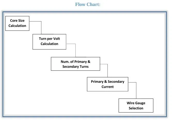
The report documents a 220 V primary and a 380 V secondary design with a 220 V tap, using an E-I laminated core. It connects core area, turns per volt, winding turns, current ratings and wire-gauge selection with fabrication. The project retains its original center-tapped title; the documented tap voltages do not establish equal secondary halves or measured output ratings.
Calculation, fabrication & redesign
- Translated the academic load/voltage brief into core and winding calculations, including turns per volt, primary/secondary turns, currents and wire-gauge requirements.
- The initial handwritten calculation used 57 VA with a 220 V primary and a 380 V secondary with a 220 V tap. This is an initial design calculation, not a verified hardware nameplate.
- The report describes difficulty sourcing the first bobbin and fitting the core after winding. The team moved to a larger bobbin and recalculated the arrangement.
- A later handwritten page records an apparent-power calculation of about 210 VA for the larger bobbin, retaining the documented primary, secondary and tap voltages. This is a separate design iteration.
- Wound and insulated the coils, assembled the E-I core and mounting hardware, and included open-/short-circuit test work in the project scope.
Design constraints
- Bobbin availability and the space required by the windings affected whether the laminated core could be fitted.
- The 57 VA and approximately 210 VA calculations belong to different design iterations; neither is presented as a measured rating of the photographed transformer.
- The supplied report has an open-/short-circuit-test page without recorded measurements.
Work & results in context
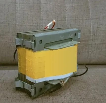
- Fabricated the transformer shown in the hardware photograph and documented a redesign around winding/core fit.
- The owner caption reports test work, but measured voltages, efficiency, regulation and test values are not established by the supplied report.
- The documented 380 V secondary with a 220 V tap describes the design arrangement, not a verified output specification or equal secondary halves.
What the redesign illustrates
- A winding calculation must fit a real bobbin and core assembly; material availability and fabrication geometry can force a new calculation.
- Design iterations and measured results need separate records so a calculated apparent-power value is not mistaken for verified hardware performance.
Further work
- A fuller technical record would require measured secondary/tap voltages and the original open-/short-circuit readings before assigning performance or a tested rating.
Visual record
Images & diagrams
Continue exploring
More engineering work
Electric mobility
Range Extended Electric Vehicle
Developing a REEV prototype for areas with limited charging infrastructure, combining electric propulsion with an engine-driven generator. FYP-1 established the architecture and integration methodology.
View projectPower systems
Micro Hydropower Plant
A completed rural-electrification design study for Kewai Village, Naran, covering the water-to-wire system and its environmental and economic feasibility.
View projectPower systems
Substation & Distribution Design
An academic layout and distribution study for mixed residential, industrial and commercial loads, using load curves to guide equipment ratings.
View project